Electrical Tester Circuit Diagram . — an electric phase tester (also known as a mains tester, line tester, or phase tester) is a basic. build and simulate circuits right in your browser. — whether you want to test a simple circuit you've made for a school project or a wall outlet in your home, there are. — electrical testing, in its most basic form, involves applying voltage or current to a circuit and comparing the measured value to an. Analog & digital circuit simulations in seconds. welcome to this comprehensive tutorial where we'll explore the intricacies of building and utilizing a components tester circuit. an interactive simulation for building circuits with various components and measuring their electrical properties on phet.
from www.youtube.com
— whether you want to test a simple circuit you've made for a school project or a wall outlet in your home, there are. — an electric phase tester (also known as a mains tester, line tester, or phase tester) is a basic. an interactive simulation for building circuits with various components and measuring their electrical properties on phet. — electrical testing, in its most basic form, involves applying voltage or current to a circuit and comparing the measured value to an. welcome to this comprehensive tutorial where we'll explore the intricacies of building and utilizing a components tester circuit. Analog & digital circuit simulations in seconds. build and simulate circuits right in your browser.
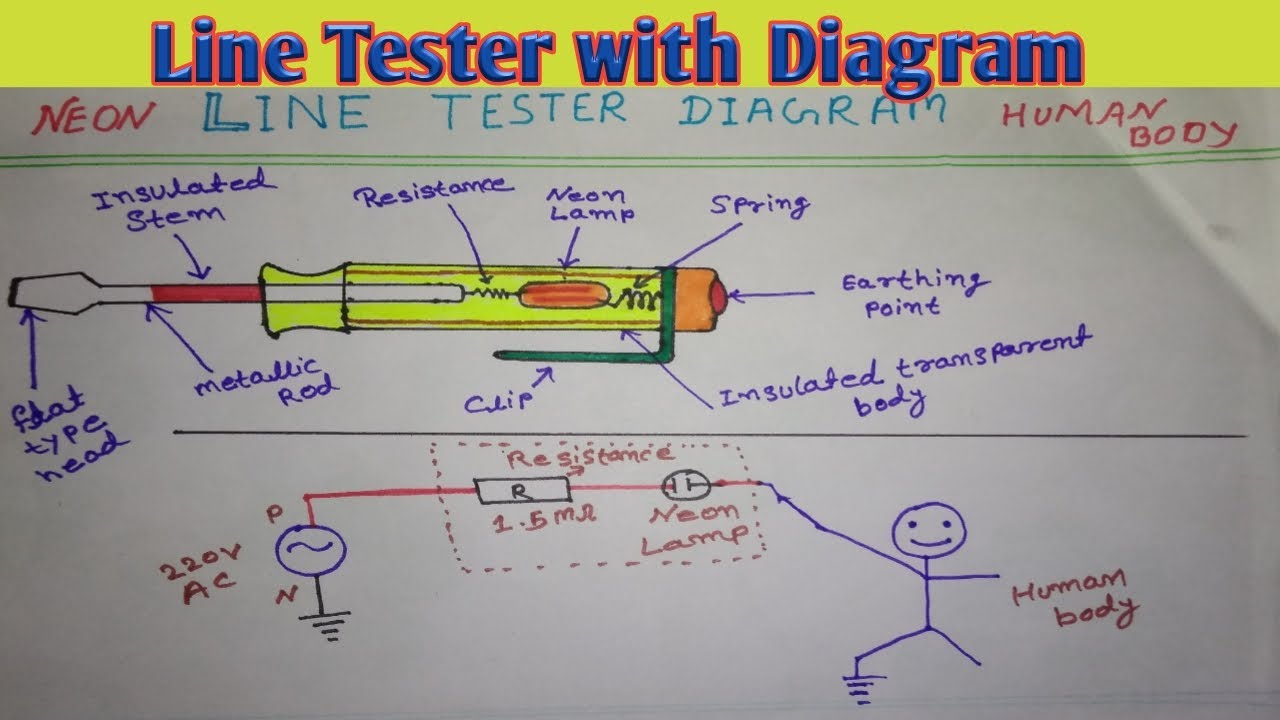
Neon Line Tester Line tester working explained with diagram How does Electric Line Tester
Electrical Tester Circuit Diagram welcome to this comprehensive tutorial where we'll explore the intricacies of building and utilizing a components tester circuit. Analog & digital circuit simulations in seconds. welcome to this comprehensive tutorial where we'll explore the intricacies of building and utilizing a components tester circuit. — an electric phase tester (also known as a mains tester, line tester, or phase tester) is a basic. — electrical testing, in its most basic form, involves applying voltage or current to a circuit and comparing the measured value to an. build and simulate circuits right in your browser. — whether you want to test a simple circuit you've made for a school project or a wall outlet in your home, there are. an interactive simulation for building circuits with various components and measuring their electrical properties on phet.
From www.nutsvolts.com
Build a Continuity Tester Nuts & Volts Magazine Electrical Tester Circuit Diagram build and simulate circuits right in your browser. — electrical testing, in its most basic form, involves applying voltage or current to a circuit and comparing the measured value to an. an interactive simulation for building circuits with various components and measuring their electrical properties on phet. — whether you want to test a simple circuit. Electrical Tester Circuit Diagram.
From www.electricaltechnology.org
How To Perform a Continuity Test for Electric Components with Multimeter? Electrical Tester Circuit Diagram an interactive simulation for building circuits with various components and measuring their electrical properties on phet. build and simulate circuits right in your browser. — an electric phase tester (also known as a mains tester, line tester, or phase tester) is a basic. — whether you want to test a simple circuit you've made for a. Electrical Tester Circuit Diagram.
From www.eleccircuit.com
Simple Universal tester circuit with VCO Electrical Tester Circuit Diagram an interactive simulation for building circuits with various components and measuring their electrical properties on phet. — whether you want to test a simple circuit you've made for a school project or a wall outlet in your home, there are. — an electric phase tester (also known as a mains tester, line tester, or phase tester) is. Electrical Tester Circuit Diagram.
From www.circuitdiagram.co
Voltage Tester Schematic Diagram Circuit Diagram Electrical Tester Circuit Diagram — electrical testing, in its most basic form, involves applying voltage or current to a circuit and comparing the measured value to an. welcome to this comprehensive tutorial where we'll explore the intricacies of building and utilizing a components tester circuit. an interactive simulation for building circuits with various components and measuring their electrical properties on phet.. Electrical Tester Circuit Diagram.
From www.electrothinks.com
Neon Line Tester Circuit Working Explanation Electrothinks Electrical Tester Circuit Diagram — whether you want to test a simple circuit you've made for a school project or a wall outlet in your home, there are. welcome to this comprehensive tutorial where we'll explore the intricacies of building and utilizing a components tester circuit. — electrical testing, in its most basic form, involves applying voltage or current to a. Electrical Tester Circuit Diagram.
From www.vrogue.co
Simple Continuity Testing Circuit Diagram Using 555 T vrogue.co Electrical Tester Circuit Diagram — whether you want to test a simple circuit you've made for a school project or a wall outlet in your home, there are. welcome to this comprehensive tutorial where we'll explore the intricacies of building and utilizing a components tester circuit. — electrical testing, in its most basic form, involves applying voltage or current to a. Electrical Tester Circuit Diagram.
From www.pinterest.com
In this post we are going to discuss a few noncontact voltage detector/tester circui Electrical Tester Circuit Diagram — whether you want to test a simple circuit you've made for a school project or a wall outlet in your home, there are. — electrical testing, in its most basic form, involves applying voltage or current to a circuit and comparing the measured value to an. — an electric phase tester (also known as a mains. Electrical Tester Circuit Diagram.
From www.electricalknowledge.com
How Does a Non Contact Voltage Tester Work? Electrical Knowledge Electrical Tester Circuit Diagram an interactive simulation for building circuits with various components and measuring their electrical properties on phet. — an electric phase tester (also known as a mains tester, line tester, or phase tester) is a basic. — electrical testing, in its most basic form, involves applying voltage or current to a circuit and comparing the measured value to. Electrical Tester Circuit Diagram.
From www.electricaltechnology.org
Cable and Wire Tester Circuit Diagram Multi Electronic Tester Electrical Tester Circuit Diagram welcome to this comprehensive tutorial where we'll explore the intricacies of building and utilizing a components tester circuit. an interactive simulation for building circuits with various components and measuring their electrical properties on phet. Analog & digital circuit simulations in seconds. — whether you want to test a simple circuit you've made for a school project or. Electrical Tester Circuit Diagram.
From circuitdatamehler.z19.web.core.windows.net
Non Contact Voltage Tester Circuit Diagram Electrical Tester Circuit Diagram Analog & digital circuit simulations in seconds. — whether you want to test a simple circuit you've made for a school project or a wall outlet in your home, there are. welcome to this comprehensive tutorial where we'll explore the intricacies of building and utilizing a components tester circuit. an interactive simulation for building circuits with various. Electrical Tester Circuit Diagram.
From guidelistgordon.z6.web.core.windows.net
Ac Line Tester Circuit Diagram Electrical Tester Circuit Diagram Analog & digital circuit simulations in seconds. — an electric phase tester (also known as a mains tester, line tester, or phase tester) is a basic. — electrical testing, in its most basic form, involves applying voltage or current to a circuit and comparing the measured value to an. build and simulate circuits right in your browser.. Electrical Tester Circuit Diagram.
From www.organised-sound.com
Diy Electrical Circuit Tester Wiring Diagram Electrical Tester Circuit Diagram an interactive simulation for building circuits with various components and measuring their electrical properties on phet. build and simulate circuits right in your browser. — whether you want to test a simple circuit you've made for a school project or a wall outlet in your home, there are. welcome to this comprehensive tutorial where we'll explore. Electrical Tester Circuit Diagram.
From diagramlibraryjulie.z13.web.core.windows.net
Electric Tester Circuit Diagram Electrical Tester Circuit Diagram an interactive simulation for building circuits with various components and measuring their electrical properties on phet. Analog & digital circuit simulations in seconds. — an electric phase tester (also known as a mains tester, line tester, or phase tester) is a basic. build and simulate circuits right in your browser. — whether you want to test. Electrical Tester Circuit Diagram.
From www.circuitdiagram.co
Simple Continuity Tester Circuit Diagram Circuit Diagram Electrical Tester Circuit Diagram — whether you want to test a simple circuit you've made for a school project or a wall outlet in your home, there are. an interactive simulation for building circuits with various components and measuring their electrical properties on phet. Analog & digital circuit simulations in seconds. — an electric phase tester (also known as a mains. Electrical Tester Circuit Diagram.
From www.homemade-circuits.com
Simple LED Forward Voltage Drop Tester Circuit Homemade Circuit Projects Electrical Tester Circuit Diagram — an electric phase tester (also known as a mains tester, line tester, or phase tester) is a basic. build and simulate circuits right in your browser. welcome to this comprehensive tutorial where we'll explore the intricacies of building and utilizing a components tester circuit. — electrical testing, in its most basic form, involves applying voltage. Electrical Tester Circuit Diagram.
From www.homemade-circuits.com
7 Simple Continuity Tester Circuits Explained Homemade Circuit Projects Electrical Tester Circuit Diagram — whether you want to test a simple circuit you've made for a school project or a wall outlet in your home, there are. Analog & digital circuit simulations in seconds. welcome to this comprehensive tutorial where we'll explore the intricacies of building and utilizing a components tester circuit. an interactive simulation for building circuits with various. Electrical Tester Circuit Diagram.
From circuitdatamehler.z19.web.core.windows.net
Non Contact Voltage Tester Circuit Diagram Electrical Tester Circuit Diagram — whether you want to test a simple circuit you've made for a school project or a wall outlet in your home, there are. welcome to this comprehensive tutorial where we'll explore the intricacies of building and utilizing a components tester circuit. — an electric phase tester (also known as a mains tester, line tester, or phase. Electrical Tester Circuit Diagram.
From www.simplecircuitdiagram.com
Continuity And Component Tester Simple Circuit Diagram Electrical Tester Circuit Diagram — electrical testing, in its most basic form, involves applying voltage or current to a circuit and comparing the measured value to an. an interactive simulation for building circuits with various components and measuring their electrical properties on phet. build and simulate circuits right in your browser. Analog & digital circuit simulations in seconds. welcome to. Electrical Tester Circuit Diagram.